We use cookies to help you navigate efficiently and perform certain functions. You will find detailed information about all cookies under each consent category below.
The cookies that are categorized as "Necessary" are stored on your browser as they are essential for enabling the basic functionalities of the site. ...
Necessary cookies are required to enable the basic features of this site, such as providing secure log-in or adjusting your consent preferences. These cookies do not store any personally identifiable data.
Functional cookies help perform certain functionalities like sharing the content of the website on social media platforms, collecting feedback, and other third-party features.
Analytical cookies are used to understand how visitors interact with the website. These cookies help provide information on metrics such as the number of visitors, bounce rate, traffic source, etc.
Performance cookies are used to understand and analyze the key performance indexes of the website which helps in delivering a better user experience for the visitors.
Advertisement cookies are used to provide visitors with customized advertisements based on the pages you visited previously and to analyze the effectiveness of the ad campaigns.
Leading the Way in Innovative Weld Purging Solutions for a Cleaner, Safer World.
We made it to the Finals of Made in UK 2024 Awards – Read More


Date: November 4-7, 2024
Location: Abu Dhabi, UAE
Booth Number: TBC

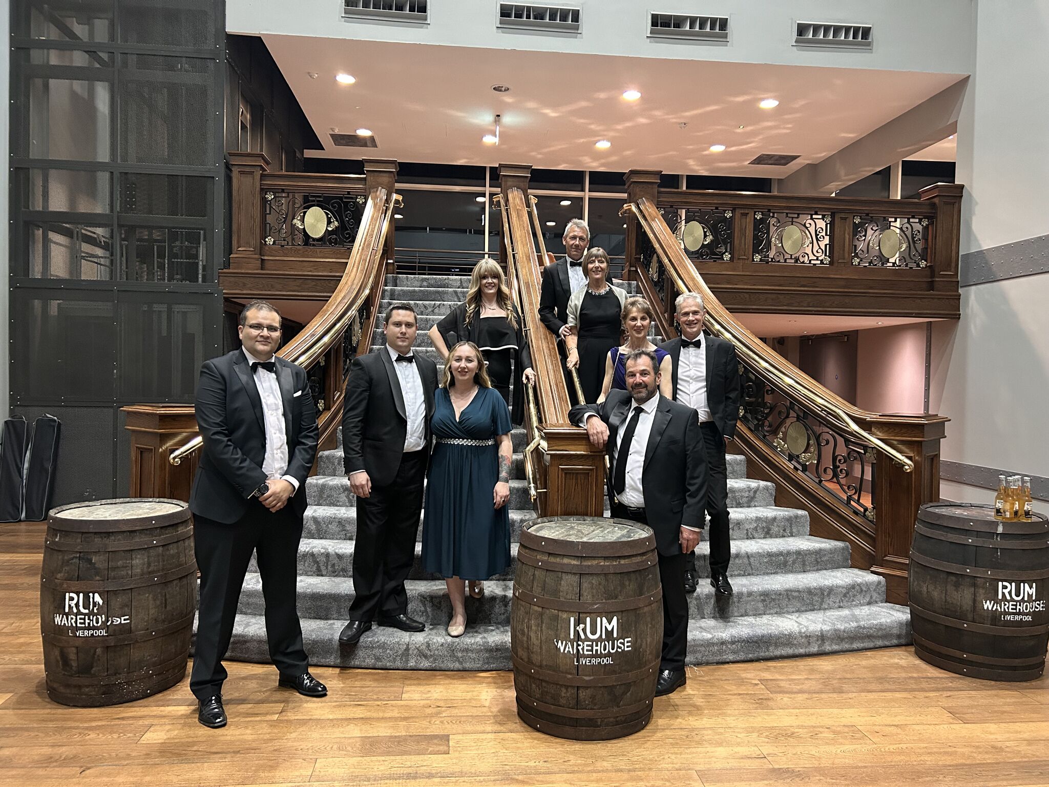
We are thrilled that Huntingdon Fusion Techniques (HFT) was shortlisted for the UK Exporter of the Year award!
Although we didn't take home the trophy, being recognised among the best in our field is an incredible honour. Thank you to our fantastic team, partners, and customers for your unwavering support. We couldn’t have achieved this milestone without you!

FabTech, the premier event for metal forming, fabricating, welding, and finishing, provides a unique platform to showcase our latest innovations.
Please join us as we demonstrate our advanced weld purging products and discuss how they can benefit your operations. Visit our booth to meet our experts, explore our cutting-edge solutions, and learn more about how we are pushing the boundaries of welding technology.
We have been informed of instances where customers are purchasing our products from unauthorised distributors and online marketplaces. Not verifying the legitimacy of the distributor poses a risk to you receiving genuine HFT products and support. We strongly advise you to take this step seriously. Please only communicate with official HFT directors and employees. If you have any concerns or need assistance, feel free to contact us at support@huntingdonfusion.com.
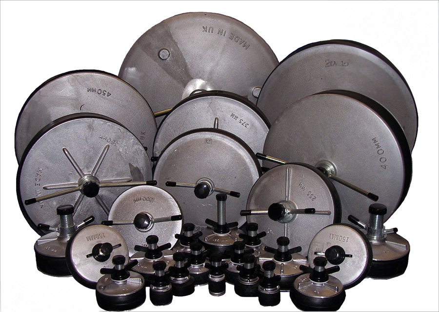
"The purge meters are second to none."
"I am a huge fan of Huntingdon products and have talked to others over the years about using them. The purge meters are second to none. I own and use regularly my PurgEye 100 and my PurgEye 300. I think somewhere, I still have my original Argweld® MKV monitor, which sadly no longer powers up. I am a scarce breed because I have 3 degrees and a complete academic understanding of metallurgy, but more importantly, welding science; I also have over 20 years of hands-on experience in welding on drill floors, firing lines, and vessel shops. I quite literally have a passion for old-fashioned welding! Excellent product, guys!"
Davina Urquhart
CITY COLLEGE AND SENIOR WELDING ENGINEER AT TRANSWELD SERVICES LTD
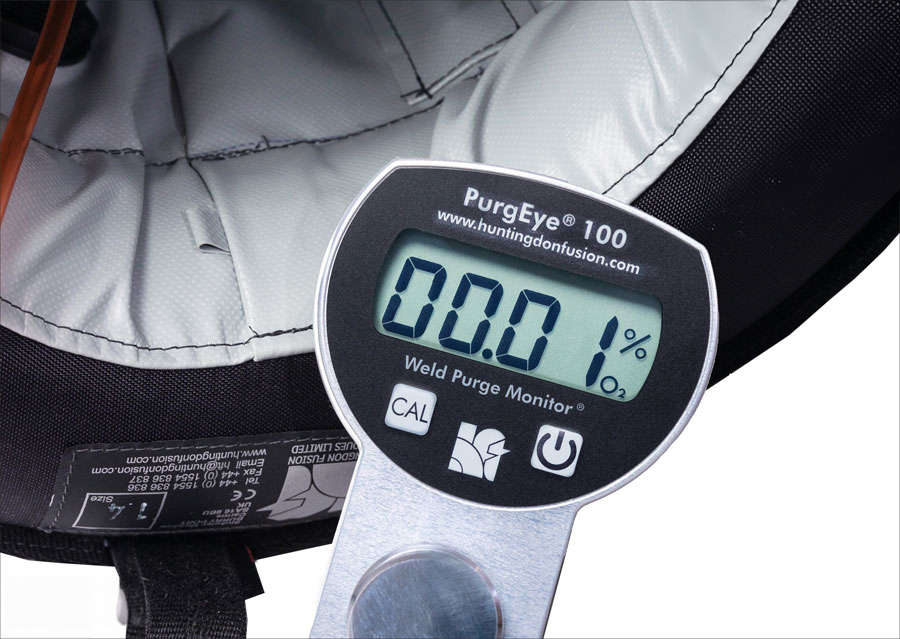
"One of the best, if not the best, residual oxygen detector instruments on the market."
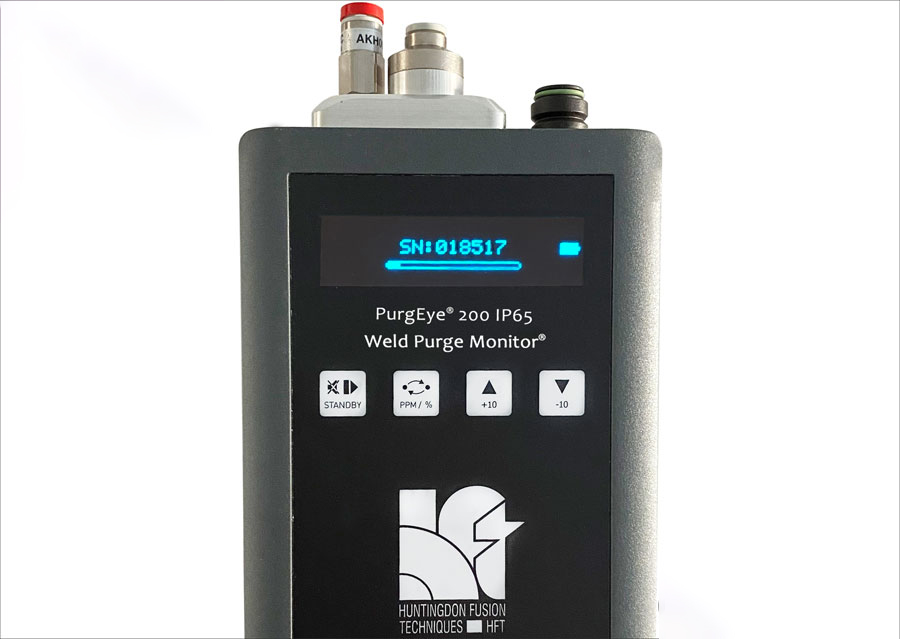
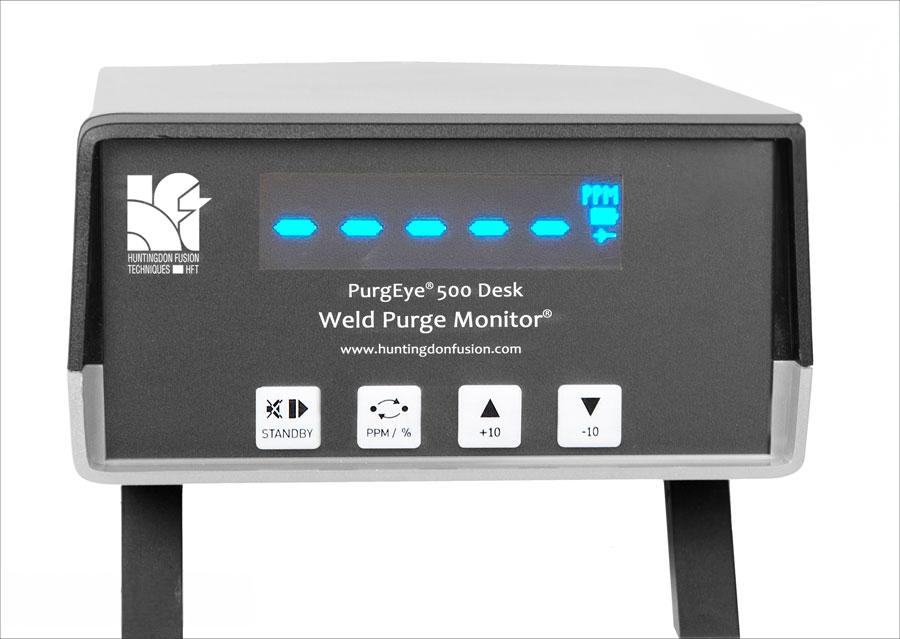
"I believe the PurgEye to be one of the best if not the best, residual oxygen detector instruments on the market with its digital residual oxygen level LED display readouts measuring as low as 0.01% and its large, user-friendly viewing screen making it easier for me to read. I also believe the PurgEye has great accuracy in residual oxygen, with speedy measurements displayed within seconds. The PurgEye is a far cry from the old school homemade 'use a cigarette lighter' to check purge gas flow system."
Construction and Maintenance
PIPING SOLUTIONS PTY LTD, AUSTRALIA
"Purge monitors are a necessity."
"I can personally vouch for purge monitors. When working with medium to large-diameter exotic pipework, they can prevent you from having a terrible day! I've only used the older model, which was a godsend. Anyone, from the welder who has had to carry out weld repairs due to root weld oxidation (or coking) on such materials, to the directors facing an expensive bill for re-work and possible tarnished company reputation, to the client with their project now running behind schedule - knows exactly what I mean. Purge monitors are a necessity."
Colin Sherriffs
WELDING AND FABRICATION INSTRUCTOR/ASSESSOR AT ITCA LTD